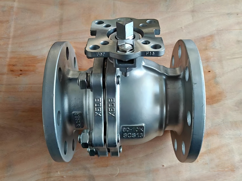
In industrial pipeline systems, Flange Ball Valves and Flange Gate Valves are both commonly used valves, but their core difference lies in the closure element: the ball valve utilizes a sphere as its closing part, which rotates 90 degrees around the valve centerline to open or close the pipeline. Among them, the JIS Flange Ball Valve, designed and manufactured in accordance with Japanese Industrial Standards (JIS), is widely used for various media such as water, oil, steam, chemicals, and natural gas due to its compact structure, reliable sealing, and easy operation, meeting diverse working condition requirements.
The JIS Flange Ball Valve mainly consists of key components such as the valve body, bonnet, ball, stem, seat, and sealing ring. Its core working principle is: by rotating the stem, the ball is turned 90 degrees, aligning or perpendicularing the ball's bore with the pipeline to allow or block the flow of media. An elastic sealing ring is used between the seat and the ball, achieving bidirectional sealing through spring preload and media pressure. The stem features a blowout-proof design and is equipped with an automatic packing compression structure, ensuring long-term sealing reliability. Additionally, injecting lubricant between the sealing surfaces forms an oil film, which not only enhances sealing but also significantly reduces operating torque.
JOEPAI, a professional manufacturer has optimized the JIS Flanged Ball Valve based on years of technical experience:
1. Dual-Lip Seal Seat: Enhances sealing performance, broadens the range of applicable media, and reduces operating torque.
2. Blowout-Proof Stem Design: A bottom-loaded structure prevents the stem from being ejected under pressure, and an embedded PTFE guide bushing reduces friction for smoother operation.
3. Fire-Safe and Anti-Static Design: Complies with API 607 standards for improved safety; an optional high-platform design allows direct mounting of actuators.
Design & Manufacturing: JIS B2071, BS5351
Face-to-Face Dimensions: JIS B2002
Connecting Flanges: JIS B2212, B2214
Testing & Inspection: JIS B2003
Fire-Safe Standard: API 607
| Item | Description |
| Common Models | Q41, Q47, etc. |
| Body Materials | WCB, A105, F304, F316, LCB, CF8, CF8M, CF3, CF3M, etc. |
| Size Range | DN15 – DN350 (½” – 14”) |
| Pressure Range | 5K, 10K, 20K, 63K |
| Temperature Range | -29°C ~ 350°C (depending on materials) |
| Actuation Methods | Manual, Gear, Electric, Pneumatic |
To ensure valve performance and service life, follow these steps during installation:
Clean the pipeline before installation to ensure no foreign matter remains.
Verify valve markings and perform full open/close tests.
Align the valve flanges with pipeline flanges and tighten bolts evenly.
Actuators (e.g., pneumatic, electric) should be installed in the specified orientation.
Operate the valve multiple times after installation to confirm smooth, non-binding operation.
Conduct sealing performance tests according to pipeline requirements.
For further details on JIS Flange Ball Valve specifications, pricing, and customized solutions, please contact us for professional selection support and technical documentation. We provide valves compliant with JIS, API, DIN and other standards, and can recommend the most suitable, cost-effective valve configuration based on your specific working conditions.